P & I diagram | P&I Diagram Full Form | P&I Diagram Means | P & I Diagram Symbols
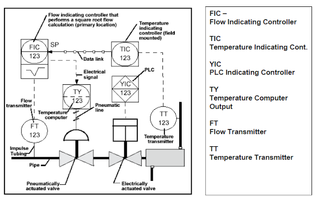
P & I Diagram stands for Piping and Instrumentation diagram. P&ID is a type of engineering drawing that depicts the process flow, equipment, and instrumentation of a plant or industrial process. While P&IDs can vary depending on the type of process being depicted. The P&ID use symbols and circles to represent each instrument and how they are inter-connected in the process.It gives the over all idea about the process.
P&ID used to describe over all plant and instrumentation.
It shows the flows in a plant and the corresponding sensors or other equipment.It gives name to each sensors and other equipment along with their parameter.
The P&ID mixes pneumatic / hydraulic elements, electrical elements and instrumentation on the same diagram.
P&ID should be included with following
- All process equipment (With its tag number)
- All pipes (With line number)
- All valves with identification no along with their type and size should be shown.
- Pumps with tag number
- All control loops and instruments with identification.
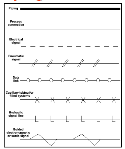
- Common Connection Lines drawing
How to read P&ID
Discrete instruments are indicated by circular elements
Shared control/display elements are circles surrounded by a square.
Computer functions are indicated by a hexagon
Programmable logic function are shown as a triangle inside a square.
TAG Descriptor
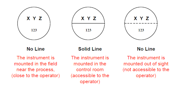
Instrument location
No Line - Instrument is mounted in the field near process (Close to the operator)
Solid line - The instrument is mounted in the control room (accessible to the operator)
Dotted line - The instrument is mounted out of sight (not accessible to the operator)
What should not be included in a P&ID
Structural or architectural details: P&IDs should focus solely on the process flow, equipment, and instrumentation. They should not include any structural or architectural details of the plant or facility.
Piping materials: P&IDs should not include information about the materials used for the piping. This information is typically included in the piping specification documents.
Equipment dimensions: While the equipment itself should be depicted on the P&ID, the dimensions of the equipment should not be included. This information is typically included in equipment data sheets.
Operating procedures: P&IDs should not include operating procedures or instructions. These are typically included in separate documents such as standard operating procedures (SOPs) or operations manuals.
Electrical details: While instrumentation related to electrical systems may be depicted on a P&ID, the P&ID should not include detailed electrical information such as wiring diagrams. This information is typically included in separate electrical schematics or drawings.
P&ID symbols for different types of equipment and instruments:
Pumps: Pumps are often represented by a circle with an arrow indicating the direction of flow. There are different types of pumps, such as centrifugal pumps and positive displacement pumps, which can be distinguished by additional symbols such as impeller blades and gear teeth.
Heat Exchangers: Heat exchangers are typically represented by two parallel lines with crosshatching between them to indicate the heat transfer process. Additional symbols may be used to indicate the type of heat exchanger, such as a shell and tube or plate heat exchanger.
Valves: There are many types of valves used in industrial processes, and each is typically represented by a unique symbol on a P&ID. For example, a gate valve is represented by a rectangle with a diagonal line across it, while a ball valve is represented by a circle with a cross inside.
Tanks: Tanks are typically represented by a rectangle with rounded corners. Additional symbols may be used to indicate the type of tank, such as a vertical or horizontal orientation or a cone-shaped bottom.
Flow Meters: Flow meters are used to measure the flow rate of fluids in a process, and are typically represented by a circle with an arrow indicating the direction of flow, and a series of diagonal lines to indicate measurement.
Control Valves: Control valves are used to regulate the flow of fluids in a process and are typically represented by a circle with a diagonal line and a smaller circle inside, which represents the valve stem.
Pressure Gauges: Pressure gauges are used to measure the pressure of fluids in a process and are typically represented by a circle with a pointer indicating the pressure reading.
FAQs
Q: What is meant by P&I diagrams?
A: P&ID stands for Piping and Instrumentation Diagram. It is a type of engineering drawing used in process control and industrial automation. The P&ID shows the piping of the process flow together with the instrumentation and control devices used to monitor and control the process.
Q: What is P and I diagram in process control?
A: The P&ID, also called a process flow diagram or process and instrumentation diagram, is a graphical representation of a process system. It illustrates the interconnection of process equipment, pipelines, valves, instrumentation, and control devices.
Q: What is the structure of P&ID?
A: A typical P&ID will show the process flow from left to right or top to bottom. It consists of a series of interconnected boxes or rectangles representing the process equipment such as pumps, heat exchangers, reactors, distillation columns, etc. These boxes are connected by lines that represent the process piping. The P&ID also includes symbols representing the control and instrumentation devices used to measure, monitor, and control the process.
Q: Why are P&ID used?
A: P&ID are used for several purposes such as:
Designing new process systems: P&ID are essential for designing new process systems as they show the layout of process equipment, piping, and instrumentation.
Understanding existing systems: P&ID can be used to understand how existing process systems are set up and how they operate.
Troubleshooting: P&ID can be used to diagnose and troubleshoot process problems as they show the location of equipment and instrumentation.
Maintenance: P&ID are used by maintenance personnel to identify equipment and instrumentation for repair or replacement.
Q: Why is P&ID important?
A: P&ID is an important tool for process control and industrial automation because it provides a clear and concise representation of the process system. It helps to ensure that all the process equipment and instrumentation are properly connected and working together to achieve the desired process outcomes. P&ID are used throughout the life cycle of a process system, from design to operation, maintenance, and decommissioning.


Very Informative Article, Keep Writing
ReplyDeleteP & I Diagram
nice information about p and i diagram can u post information about Reactor Design
ReplyDelete