During Induction motor start-up without Star Delta Starter, in rush currents of up to approximately eight times the rated current and the high starting torque linked to this is developed. The high starting currents often lead to voltage drops in the supply network and the high starting torque put the mechanical elements under considerable strain. This direct start method causes a disturbance of voltage on the supply lines due to large starting current surges. In electrical power systems, various connection types are used to connect loads, transformers, and generators. One of the most common types of connection is the star connection. This article will explain the basics of star connection, including its advantages and applications & Control Diagram of Star Delta Starter.
Control Diagram of Star Delta Starter | Star Delta Starter Control Diagram
- Star-delta connection is a type of electrical connection used for three-phase motors.
- It is commonly used in applications where the motor needs to start with a low current and then switch to a high current.
- In a star-delta connection, the motor is initially connected in a star configuration, where each phase is connected to a common point.
- During the starting phase, the motor draws a low current because the voltage applied to each winding is reduced.
- Once the motor reaches a certain speed, the connection switches to a delta configuration, where each winding is connected to the next in a loop.
- In the delta configuration, the motor draws a higher current and can operate at full load.
- Star-delta connections can help reduce the starting current of a motor by up to 33%, which can help prevent damage to the motor and reduce power consumption.
- However, the switch between star and delta configuration can cause a momentary interruption in power, which can affect other equipment connected to the same power source.
What is Star Connection?
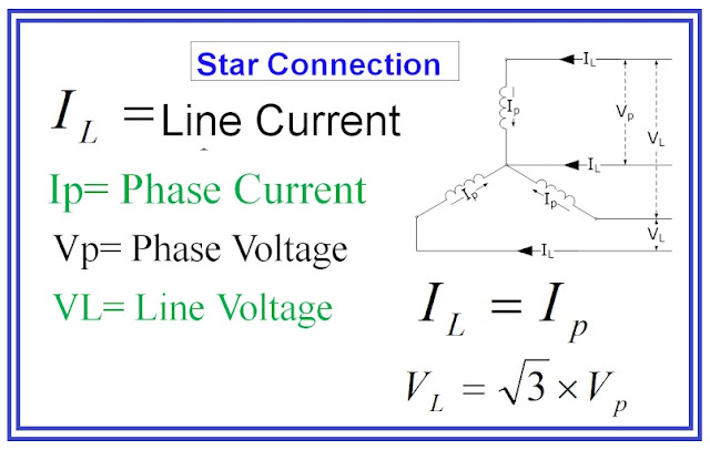
A star connection, also known as a Y connection, is a type of connection in which three identical components are connected to a common point, forming a Y shape. In electrical power systems, the three components are usually three-phase AC voltage sources or loads.
To limit the starting current surge, large induction motors are started at reduced voltage and then have full supply voltage reconnected when they run up to near rotated speed.
Generally above 5 HP and upto 25 HP star delta startup is used. For star delta stater, the motor connection there are 6 cables from control panel and 6 terminals at induction motor ( U1,U2,V1,V2,W1,W2)
Voltage and Current Calculations in Star Connection
In a star connection, the line voltage (VL) is the voltage between any two of the three line conductors, while the phase voltage (Vφ) is the voltage between any line conductor and the common point. The relationship between line voltage and phase voltage is given by the following equation:
VL = √3 x Vφ
The current in each line conductor (IL) is the same as the current in the corresponding phase conductor. The total current (IT) in the star connection is given by the following equation:
IT = √3 x Iφ
where Iφ is the current in each phase conductor.
Star Delta connection basics
Startup of Motor with Star Delta Starter
After motor run-up, in most cases an preset timer relay controls the switch-over from star to delta. The run-up using star connection should last until the motor has reached the approximate operational speed, so that after switching to delta, as little post acceleration as possible is required. Post-acceleration in delta connection will result high currents as seen with direct-on-line starting. The duration of start in star connection depends on the motor load. During delta connection, the full mains voltage is applied to the motor windings.
For changeover from star to delta, the six leads of the motor winding are connected onto terminals. The contactors of a star-delta starter switch over the windings accordingly.
Starting in star, the main contactor connects the mains to winding endings U1, V1, W1.
The star contactor shorts winding endings U2, V2, W2. After successful run-up, the star contactor switches itself off and the delta contactor connects terminals U1/W2, V1/U2, W1/V2.
When changing from star to delta, attention must be given to the correct phase sequence, i.e. the correct connection of the conductors to motor and starter. Incorrect phase sequence can lead to very high current peaks during the cold switch-over pause, due to the easy torque reduction following re-start. These peaks can damage the motor windings and stress the control gear unnecessarily. The rotation of the motor has to be considered as well.
Control Diagram of Star Delta Starter
Motor Protection and Contactor Rating
The overload relay is connected in the motor line (F2 in above fig). Therefore, the current to be adjusted is lower than the motor’s rated current by a factor of 1√3 = 0.58.
Contactor must be sized in as per following currents:
• Main contactor K1 0.58 IFL
• Delta contactor K2 0.58 IFL
• Star contactor K3 0.34 IFL
(IFL is rated motor current)
Advantages of Star Connection
One of the main advantages of star connection is that it provides a neutral point for grounding. This makes it easy to protect equipment and personnel from electrical faults. Star connection also allows for easy voltage transformation, as the phase voltage and line voltage are related by a fixed factor (√3). Additionally, the use of a star connection results in a balanced load on the three phases, which reduces the impact of unbalanced loads on the power system.
Applications of Star Connection
Star connection is commonly used in three-phase AC power systems for connecting motors, transformers, and generators. It is also used in the distribution of power to residential and commercial areas.
Highlights of star-delta startup methods
- Reduced starting torque
- Reduced starting current (upto 2.6 times)
- Mechanical load on changeover from star to delta
- Six connection cables
- Current peak on changeover from star to delta
Conclusion
Star connection is a widely used type of connection in electrical power systems. It provides numerous advantages, including easy voltage transformation, balanced load distribution, and a neutral point for grounding. Understanding the basics of star connection is essential for anyone working with electrical power systems.
Frequently Asked Questions (FAQ)
What is a star-delta connection?
A star-delta connection is a type of three-phase connection used in electrical power systems to start and run large motors. It involves switching the motor from a star connection, which reduces the voltage applied to the motor windings, to a delta connection, which provides the full voltage. This helps to reduce the starting current and torque, which can prevent damage to the motor and reduce the impact on the power system.
What is difference between Star and delta connection?
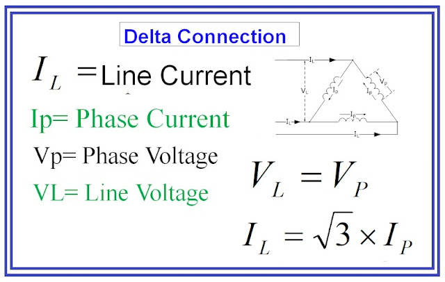
Star and delta connections are two different types of three-phase connections used in electrical power systems. In a star connection, three identical components are connected to a common point, forming a Y shape. In contrast, a delta connection is a triangular arrangement in which each component is connected to the component adjacent to it, forming a delta shape. The main difference between these connections is the relationship between line voltage and phase voltage. In a star connection, line voltage is √3 times the phase voltage, while in a delta connection, line voltage is equal to the phase voltage. Additionally, the current in a star connection is divided between the three components, while in a delta connection, the current flows through each component.
What is the formula of reactive power in 3-phase star connection?
The formula for reactive power in a 3-phase star connection is Q = √3 × VL × IL × sin(θ), where Q is the reactive power, VL is the line voltage, IL is the line current, and θ is the phase angle between the voltage and current. Reactive power is an important factor in electrical power systems, as it represents the power consumed by inductive and capacitive loads and affects the overall efficiency of the system.
What is the reactive power of 3-phase circuit?
Reactive power is a type of electrical power that does not perform any useful work but is necessary for the functioning of inductive loads in a 3-phase circuit. It is measured in volt-amperes reactive (VAR) and is a result of the phase difference between the voltage and current in inductive or capacitive loads. Reactive power is required to produce the magnetic fields that are necessary for the operation of motors, transformers, and other inductive loads in a 3-phase circuit.


Good Blog about
ReplyDeleteStar Delta Starters connections.