If you are looking to protect your Variable Frequency Drives (VFDs) and improve their efficiency, line reactors and load reactors are essential components to consider. Line reactors are designed to reduce harmonic distortion, minimize voltage spikes, and improve power factor, while load reactors can reduce motor noise and improve the stability of the load. These reactors act as a buffer between the power source and the VFD, protecting the components from stress and preventing premature failure. By improving the power quality and efficiency of your VFD system, reactors can help you save energy and reduce costs in the long run. Whether you are using VFDs in pumps, fans, conveyors, or HVAC systems, adding line and load reactors to your installation can provide significant benefits.
Line reactors for VFDS | Line reactor | Vfd Line Reactor | What Is Line Reactor
- Line reactors are electrical components designed to protect VFDs by reducing harmonic distortion, minimizing voltage spikes and transients, and improving power factor.
- They are installed on the input side of VFDs and act as a buffer between the power source and the VFD.
- Line reactors are essential for ensuring the longevity and reliability of VFDs by reducing stress on the components, preventing overheating and premature failure.
- They can also improve the efficiency of VFDs by reducing power losses, lowering energy consumption, and improving power quality.
- Line reactors come in different sizes and ratings, depending on the voltage and current requirements of the VFD.
- They are available in both 3-phase and single-phase configurations, and can be installed in a variety of applications, including pumps, fans, conveyors, and HVAC systems.
- It is important to select the right size and type of line reactor for your VFD application to ensure optimal performance and protection.
One of the primary benefits of using Line reactors for VFDS is that they help to reduce harmonic distortion in the power supply. When a VFD operates, it can produce harmonics that can cause problems with other electrical equipment on the same power system. Line reactors act as an impedance in the system, reducing the amount of harmonics that are produced.

Another benefit of using VFD line reactors is that they help to protect the VFD and the motor from power surges and other electrical disturbances that can occur on the power system. The line reactor acts as a buffer, absorbing any spikes or surges in the power supply before they can reach the VFD or motor.
Line reactors for VFDS also help to improve the power factor of the VFD system. Power factor is a measure of how efficiently the electrical power is being used. A low power factor can result in higher energy costs and can cause other problems on the power system. By using line reactors, the power factor of the VFD system can be improved, leading to greater efficiency and lower costs.
Choke / Reactors
Line (Input side) and load(Output side)reactors are installed
Reactor is
basically an inductor.
Physically it
is simply a coil of wire that allows a magnetic field to form around the coil
when current flows through it. When energized, it is an electric magnet with
the strength of the field being proportional to the amperage flowing and the
number of turns. A simple loop of wire is an air core inductor. More loops give
a higher inductance rating. Often some ferrous material such as iron is added
as a core to the winding. This has the effect of concentrating the lines of
magnetic flux there by making a more effective Inductor.
An inductor has the characteristic of storing energy in the magnetic field and is reluctant to a change in current. The main property of a reactor is its inductance and is measured in Henrys, mh, µh
In a DC
circuit (such as that of the DC link bus in an AC drive), an inductor simply
limits the rate of change of current in the circuit since current in an
inductor wants to
continue to flow at the given rate for any instant in time.
i.e. an
instantaneous increase or decrease in applied voltage will result in a slow
increase or decrease in current. Conversely, if the rate of current in the
inductor changes, a corresponding voltage will be induced. equation V=L (di/dt)
for an inductor where V is voltage, L is inductance and (di/dt) is the rate of
change of current in
amps per second, we can see that a positive rise in current will cause a
voltage to be induced.
The equation
for the reactance of an inductor is XL=2 π f L.
Where XL is
inductive reactance in Ohms, F is the applied frequency of the AC source and L
is the inductance value of the reactor. As you can see, the reactance and therefore the impedance of the reactor is higher with a higher inductance value. Also, a given inductance value will have a higher impedance at higher frequencies. Thus we can say that in addition to limiting the rate of rise in current, a reactor adds impedance to an AC circuit proportional to both its inductance value and the applied frequency.
A Reactor at the Input to reduce Harmonics:
As we know, most standard “six pulse” drives are nonlinear loads. They tend to draw current only at the plus and minus peaks of the line. Since the current wave-form is not sinusoidal the current is said to contain “harmonics”.
For a standard 3 phase input converter (used to convert AC to DC) using six SCR’s or six diodes and a filter capacitor bank as shown in figure 1 below

Fig 1 Without Reactor
Three phase input current may contain as much as 85% or more total harmonic distortion. Notice the high peaks.
If a line reactor is installed as in figure 2, the peaks of the line current are reduced and somewhat broadened out. This makes the current somewhat more sinusoidal, lowering the harmonic level to around 30-35% when a properly sized reactor is used. This effect is also beneficial to the DC filter capacitors. Since the “ripple current” is reduced.
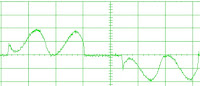
Fig 2 With Reactor at input before rectifier
The capacitors can be smaller, run cooler and last longer. Though harmonic mitigation is an important reason to use a line reactor, most drives at the 10 horsepower rating and above include a “DC link choke” as seen in figure 3. The link choke is a reactor put in the DC bus between the Rectifier bridge and the capacitor bank. It can provide the necessary harmonic mitigation and since it is in the DC bus, it can be made smaller and cheaper than the 3 phase input reactor.
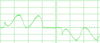
Fig 3 DC link reactor
Difference between load reactors, dv/dt filters, and sinus filters
Purpose:
Spike protection and long distance motor connection in respect to the drive.
Solutions:
There are three different types of protection that can be added to the output of a drive. These are load reactors, DV/DT filters, and Sinus filters. The distance that a motor mounted in respect to the drive is greatly increased as you go from left to right as mentioned above from load reactors to sinus filters.
Load reactors are your basic motor protection units where they provide an increase in inductance on a long motor cable run.
DV/DT filters also called motor protection filters have a longer range motor protection compared to load reactors and have built in technology to prevent spikes to the motor.
Sinus filters have the longest range of motor protection. They are designed to clean up the PWM wave coming out of the drive and have it resemble an AC sign wave as best as possible going to the motor.
A Reactor acts as line voltage buffer:
Sometimes switchgear on the line such as contactors and disconnects can cause line transients, particularly when inductive loads such as motors are switched off. Then voltage spike may occur at the input to the drive that could result in a surge of current at the input. If the voltage is high enough, a failure of the semiconductors in the DC converter may also result. Sometimes a reactor is used to “Buffer from the line”. While a DC link choke, if present, will protect against a current surge, it cannot protect the converter from a voltage spike since a link choke is located after the converter. The Semiconductors are exposed to whatever line voltage condition exists. Hence a reactor at the input to the drive is a better solution would be to attenuate the voltage spike at the source with a snubber circuit.
A reactor does not fix grounding problems also does not it provides isolation.
Reactors at the drive output to reduce the effect of reflected wave: (To nullify capacitance effect)
A reactor at the output of a drive is installed in order to prevent a reflected wave voltage spike when long motor leads are required. Though the reactor will slope off the voltage rise time providing some benefit, It is not likely to limit the peak voltage at the motor. In some cases, a resonance can be set up between the cable capacitance and reactor that causes even higher voltages to be seen at the motor. In general, a motor terminator is a better solution. If a reactor is installed at the output, it is most likely part of a specially designed “reflected wave reduction” device that also has damping resistors in parallel. If a reactor is used at the output, it should be located as close to the drive end as is possible. Figure 4 shows the motor voltage before and after the installation of a reactor. The DC bus voltage is shown for reference. Notice that the rise times are different, the peak voltage is about twiceReactor Rating:
Fig 4
An Output or
load reactor is used to protect the motor if the cabling distance between the
VFD and motor is very long. The drive
generates a high frequency PWM three-phase output and noise spikes are
generated on the leading edge of these signals. These noise spikes get amplified due to the long cable lengths and the
additional capacitance of the cable. The
resulting voltage can exceed the motor’s peak voltage rating where insulation
breakdown occurs.
The general rule of thumb is that an output
reactor should be used if the motor wiring is over 100 feet, but this value
varies depending on the motor. If the motor meets the NEMA Part 31 standard, it
is possible to have as much as 300 ft of cabling without a reactor.
If the
distance is between 500 and 1000 ft, then use a special type of a dV/dT filter,
as it provides better protection at these extreme distances. It also varies
depending on output cable specs, shielding, power conditions, and noise
suppression as well as isolation techniques. Load reactors are connected in
series between the VFD Controller and the motor. The reactor should be mounted
as close to the drive as possible
Reactor Design / Rating
First thing it should have a high enough current rating. In terms of the impedance value, you will usually find that 3% to 5% is the norm with most falling closer to 3%. A 3% reactor is enough to provide line buffering and a 5% reactor would be a better choice for harmonic mitigation if no link choke is present.Output reactors, when used, are generally around 3%. This % rating is relative to the load ordrive where the reactor impedance is a % of the drive impedance at full load. Thus a 3% reactor will drop 3% of the applied voltage at full rated current. To calculate the actual inductance value we would use the following formula. L =XL/(2π f) Where L is inductance in Henrys, XL is inductive reactance or impedance in Ohms and F is the frequency. In general Frequency will be the line frequency for both input and output reactors.e.g.. If a 3% reactor was required for a 100 amp 480 volt drive, a 100 amp or larger current rating would be required. The drive impedance would be: Z=V/I or 480/100 = 4.8 ohms. 3% X 4.4 ohms = 0.114 ohms inserting this 0.114 impedance in the equation for inductance we get a value of about 300 µh

When to Use Line Reactors (Input Chokes)
Line commutating chokes are used to smooth voltage peaks (line disturbances), or to bridge commutating dips. In addition, line commutation chokes reduce the effects of harmonics on the drive, and on the power supply.
If the short circuit capability of the line supply is >100 times larger than the nominal input current of the drive then a line commutation reactor must be used. If the capability of the line supply is unknown then a line-commutating reactor should also be used.
When to Use Load Reactors (Output Chokes)
Load reactors should be used when motor cables exceed the following lengths:
For drives 0.16 – 100HP, 150 Feet (Shielded) 300 Feet (Unshielded)
For drives 125 – 300HP, 300 Feet (Shielded), 450 Feet (Unshielded)
Motor Failures
Sometimes motors that have operated for years trouble free, suddenly fail a few weeks after the installation of an VFD. The mode of failure is usually a winding failure caused by voltage overshoot.
Mostly the failure usually occurs in the first turn, as either a phase-to-stator short or phase- to-phase short, Research has proved that due to fast switching of the IGBTs along with an excessive lead length between motor and VFD contribute to reduced motor life.
To understand how VFD cause a motor to deteriorate more quickly, two phenomenon need to be understood. The first is the reflected wave or standing wave condition, and second is voltage overshoot, also known as a tank circuit or resonant circuit condition. Both these two phenomenon may be analyzed differently, but in practice the solutions are the same.
By viewing the lead length as a transmission line circuit, the following formulas may be
applied to determine the critical length or lead length where a voltage reflection should take place.
Critical length is determined by the formula;
V=Co/e , t = L/v
v = velocity of the progressive wave (ms),
Co = 3 x10e8 meters/sec (velocity of light)
e = 3.5 (approx. specific inductivity of the cable)
t = rise time of voltage pulse,
L = length of transmission line
The next equation relates the rise time of the IGBT (t) to the critical length (L) of the transmission line.
L = t/0.00624(ms)
When this length is exceeded, a standing wave may be generated. Since the rise time of the PWM Drive output is generally from 0.1 to 0.3 ms, typically, the minimum distance required for a surge voltage to appear is 16.0 to 48.0 m. or 52.0 to 156 ft.
Voltage Overshoot
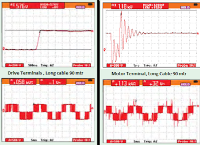
Effect on Motor: The overshoot (ringing), is a function of the energy stored in the leads during the rise time of each output voltage pulse. The amount of inductance is a function of the lead length used between the motor and the VFD. Inductance increases the amount of time it takes to charge the capacitance of the motor, which increases the amount of energy in the leads. When the motor charges to the correct voltage potential, the remaining energy in the leads continues to charge the motor voltage, thus causing voltage overshoot.
In fact, if the lead lengths are long enough, the motor terminals may see twice the DC Voltage of the VFD. It can be stated that the greater the distance between motor and VFD, the more voltage overshoot.
Maximum voltage overshoot is calculated as follows:
Input Voltage (rms) x 110% = Maximum Input Voltage, Due to High Line Condition
Vmax x 1.35 = Maximum DC Bus Voltage
Max. DC Bus Voltage x 2 = Max. Overshoot Voltage
Corona Effect
To understand why the motor deteriorates due to voltage overshoot, it is important to understand what corona is. It is generally understood that between current carrying conductors, a relative voltage potential exists; the result is an established electric field. It is possible that the electric field strength around the conductors can be high enough to cause the air to break down. The air breaks down because there is enough energy to ionize oxygen
(O2) to ozone (O3). Ozone is highly reactive and attacks the organic compounds in the insulation system. The additional oxygen in the insulation causes it to deteriorate. The corona will start when the voltage potential in the conductors reaches a certain threshold called the corona inception voltage. Corona inception voltage (CIV) is a function of spacing, type of insulation, temperature, surface features, and humidity.
The oscilloscope graphs shown below explain how voltage overshoot occurs at motor end due to long cable.
Three Phase Output Reactor
A reactor located at the output of the VFD will lower the voltage stress applied to the motor windings.
The rise time of the output pulse will be reduced thus reducing the dV/dT. This is very effective at lengthening motor life. The output reactor saves approximately 75% of all premature motor failure problems associated with long lead lengths. Typically, 3%and 5% impedance reactors are used.
Output reactor reduces the voltage overshoot by about 80%, which will be within safe limits for motor windings.
Reactor is required
To add Line Impedance.
To provide some light buffering against low magnitude line spikes.
To reducing Harmonics (When no DC link choke is present).
To compensating for a low inductance motor.
Only as part of a filter for reflected wave reduction.
Summary:
Reactors can be helpful in providing some line buffering or adding impedance especially for drives with no DC link choke. For small drives they may be needed to prevent inrush or provide reduction in current harmonics when many small drives are located at one installation. At the output they should only be used to correct low motor inductance and not as a motor protection device.


Thank you so much for this information. if you want to buy Special Purpose Transformer in India, Visit Transformer Manufacturers in pune, One of the best Transformer Manufacturers in India.
ReplyDeleteThank you so much for this information. If you are looking for Transformers Manufacturers in Pune , You may visit Trutech Products, One of the best Transformer Manufacturers in India.
ReplyDeleteThanks sharing Posts..
ReplyDeleteVFD Drives Suppliers in Chennai
FUJI Vfd Suppliers in Chennai
Push Button Supplier in Chennai
Thanks for sharing this informative post with us.
ReplyDeleteIf you are searching Best Transformer Manufacturers in India, and want to buy any kinds of Transformers so, Trutech Products is one of the prominent Transformer Manufacturers In Mumbai.
Transformer Manufacturers in Pune