Field devices in automation are critical components in industrial control systems, directly interacting with physical processes. They are responsible for collecting data from the environment and executing commands to control various systems, such as manufacturing processes, utility grids, and transportation systems.
Types of Field Devices:
Sensors:
- Purpose: Measure physical properties like temperature, pressure, level, flow, and proximity.
Examples:
- Temperature sensors (RTD, thermocouples)
- Pressure transducers
- Flow meters
- Proximity sensors (inductive, capacitive)
Actuators:
- Purpose: Convert electrical signals into physical movement or actions to control a process.
Examples:
- Valves (pneumatic, hydraulic, or electric)
- Motors (AC/DC motors, stepper motors)
- Solenoids
Transmitters:
- Purpose: Convert sensor data into a standardized signal that can be transmitted to a control system.
Examples:
- 4-20 mA transmitters for pressure or temperature
- Wireless transmitters for remote monitoring
Controllers:
- Purpose: Process data from sensors and send commands to actuators.
Examples:
- Programmable Logic Controllers (PLCs)
- Distributed Control Systems (DCS)
- Process controllers
Switches and Relays:
- Purpose: Act as control elements for switching circuits on and off or for safety purposes.
Examples:
- Limit switches
- Pressure switches
- Solid-state relays
Communication Protocols:
Field devices often communicate with a centralized control system using specific industrial protocols, such as:
- HART (Highway Addressable Remote Transducer): Used in smart field instruments, often overlaid on the 4-20 mA signal.
- Modbus: A widely-used protocol for communication in SCADA systems.
- PROFIBUS/PROFINET: For fieldbus communication in factory and process automation.
- Foundation Fieldbus: Provides digital communication for sensors and actuators.
- Wireless protocols: Zigbee, WirelessHART for wireless communication.
Role in Automation:
- Data Acquisition: Sensors gather real-time data for process monitoring.
- Control Execution: Actuators and controllers ensure that the process operates within desired parameters.
- Feedback Loop: Communication between the field device, controller, and actuator forms a feedback loop, essential for process control.
- Safety: Field devices are often integrated into safety systems to ensure that processes operate safely and effectively.
NO NC concept
It is very important to keep in mind that the "normal" contact status of a process-actuated switch refers to its status when the process is absent and/or inactive, not "normal" in the sense of process conditions as expected during routine operation. For instance, a normally-closed low-flow detection switch installed on a coolant pipe will be maintained in the actuated state (open) when there is regular coolant flow through the pipe. If the coolant flow stops, the flow switch will go to its "normal" (unactuated) status of closed.


--------------------------------------------------------------------------------------------------------------------------
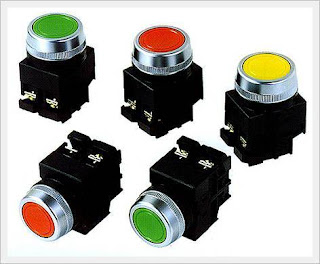
Push buttons
A Push-button is a simple switch mechanism for controlling some aspect of a machine or a process. Buttons are typically made out of plastic The surface is usually flat or shaped to accommodate the human finger or hand, so as to be easily depressed or pushed.
Buttons are most often biased switches, though even many un-biased buttons (due to their physical nature) require a spring to return to their un-pushed state.
Different people use different terms for the "pushing" of the button, such as press, depress, mash, hit, and punch.
A general-purpose push button switch is used for controls, e.g., to start machine operation or to switch modes.
-------------------------------------------------------------------------------------------------------------------------
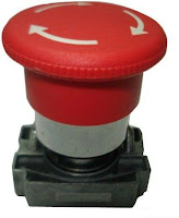
Emergency Switch
An emergency stop push button switch is used as a safety measure to stop immediately machine or any electromechanical assembly as a safety measure in emergency situations
It has direct opening mechanism installed on the NC contact.
It has a self-holding function.
Emergency pushbutton is always "Mushroom" head design.
Its color is always red
--------------------------------------------------------------------------------------------------------------------------
Binary means "two states." The two states are sometimes called "1" and "0", or called "true" and "false", or called "on" and "off", (or other names.) The essential characteristic is that a single binary device can be in just one of two possible states.
A bit is a single on/off value.
A light dimmer is not a binary device: it has many positions between off and fully on. If you want a light dimmer to be set to 25%, you must carefully adjust it
A good example is a toggle switch, such as a light switch. You can turn it on or off but not (in normal operation) anything else. A light switch holds one bit of information
An analog signal may continuously change in value. Its values can be anything within a range of values, and its exact value at any time is important.
E.g Temperature of Oven which is not 1 or 0 its value within range of temp.
.
Cable Length for Analog Sensors
Here we will see maximum recommended cable length for analog sensors.
• Analog Voltage Signals (0…10V, -10…+10V, etc): Generally, it is recommended that cable length for analog voltage signals should be limited to 50 feet
• Analog Current Signals (0-20mA, 4-20 mA): Typical industrial position sensors with an analog current interface can offer significantly longer cable lengths compared to comparable voltage interfaces. Generally analog current signals can offer cable lengths up to 500 feet
Both of above signals must be properly terminated, shielded cable.
Also the cable is not routed near high-energy AC sources, against which even a shielded cable offers little protection.
--------------------------------------------------------------------------------------------------------------------------
A proximity sensor is able to detect the presence of nearby objects without any physical contact. Inductive proximity sensors are used for non-contact detection of metallic objects.
A proximity sensor often emits an electromagnetic field or a beam of electromagnetic radiation (infrared, for instance), and looks for changes in the field or return signal. Their operating principle is based on a coil and oscillator that creates an electromagnetic field in the close surroundings of the sensing surface. The object being sensed is often referred to as the proximity sensor's target. The presence of a metallic object (Target) in the operating area causes a dampening of the oscillation amplitude.
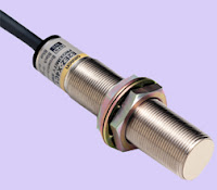
The rise or fall of such oscillation is identified by a threshold circuit that changes the output of the sensor. Different proximity sensor targets demand different sensors. For example, a capacitive or photoelectric sensor might be suitable for a plastic target; an inductive proximity sensor always requires a metal target.
The maximum distance that this sensor can detect is defined "nominal range". Some sensors have adjustments of the nominal range or means to report a graduated detection distance.
Proximity sensors can have a high reliability and long functional life because of the absence of mechanical parts and lack of physical contact between sensor and the sensed object.
Outputs: DC Voltage
3 & 4 wire DC: These amplified D.C. sensors contain an output amplifier. They are supplied as 3 wire with function N.O. or NC and as 4 wire with complementary outputs (NO + NC) in the types NPN and PNP.

2 wire DC: These sensors contain an output amplifier with the function N.O. or N.C. that can pilot a load connected in series. In this system a residual current flows through the load even when in the open state and a voltage drop occurs to the sensor when it is in the closed state.
AC Voltage
2 wire AC: These are two-wire sensors that contain a thyristor output amplifier. In this system a residual current flows through the load even when in the open state and a voltage drop occurs to the sensor when it is in the closed state.
Inductive & Capacitive Type Proximity Sensors
Inductive Proximity sensors use a magnetic field to detect objects. Capacitive Proximity sensors use an electric field. In order to be sensed by an inductive Proximity sensor an object must be conductive. This limits suitable targets to metal objects (for the most part). In order to be sensed by a capacitive Proximity sensor the target doesn’t need to be conductive. A capacitive Proximity sensor will react to an object acting as a dielectric material as well as a conductive object. This makes metal and non-metal objects suitable targets.
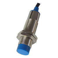
Flush or Non-Flush type Proximity Sensors
Flush-style sensors actually have a shield that restricts the magnetic field so that it only radiates out of the face of the sensor. Flush-style, or shielded sensors can be mounted flush in a metal bracket or even in your machine without the metal causing the sensor to false trigger. When mounting two shielded inductive proximity sensors next to each other, you should typically leave one diameter of the sensor between adjacent sensors.

The shielded-style of sensor will typically have approximately one-half of the sensing distance that a non-shielded version will have.
For example, a M12 shielded inductive sensor will have a sensing distance 2mm whereas a non-shielded version will have a sensing distance of 4mm. Although shielded style sensors have a shorter sensing range they can be fitted in a machine or a bracket that will offer protection against damage.
Non-flush, or unshielded sensor, does not have the shield around the end of the sensor so the field can radiate from the face to the sides of the sensor in a larger pattern. This style of sensor cannot be mounted flush in a metal bracket, as the metal will cause the sensor to actuate. When installing a non-shielded sensor in metal you should have one diameter from each edge of the sensor to the nearest metal flange.
------------------------------------------------------------------------------------------------------------------------
Photoelectric sensors
Photoelectric sensors provide non-contact accurate detection of targets. They emit infrared, red or laser light and the target breaks the light beam or reflects the beam back to the sensor to activate the sensor output.
Photoelectric sensors can check for presence, color, distance, size, shape, and many more targets attributes. They can perform these functions at longer distances than other sensing methods while providing numerous mounting options and flexibility.
Photoelectric sensing modes are divided into three primary types, those being through-beam, retro-reflective and diffuse.
Photoelectric sensors Applications
• Clear and transparent detection
• Measuring
• Detecting marks
• Parts detection
• Parts counting
• Color verification
Through-Beam
Through-beam sensing, also known as transmitted beam, opposed mode, direct-scanning, or break-beam is usually the first choice in solving photoelectric applications.
The emitter and receiver are in separate housings and are aimed directly opposite each other or in direct line of sight. When the target breaks the light beam, which can be infrared, visible red or laser, the output is activated.

Through-beam sensors offer the longest sensing range of up to 100 meters. The target should be larger than the effective beam or if the application requires detecting smaller parts, apertures can be added.
The high gain of these sensors will burn through smoke, fog, haze, dust, mist, coolant, and dirt allowing them to be used in harsh or contaminated environments.
These sensors can detect objects independent of color, reflectivity and are not affected by second surface reflections.
Applications
• Parts counting
• Tool verification
• Stack height
• Conveyors, package detection
• Skewed lid detection
• Part presence
• Error proofing
Retro Reflective photoelectric sensor that requires a reflector
Retro-reflective sensors sometimes referred to as reflex, retro and polarized retro-reflective, have the emitter and receiver housed in a single housing. A cube style reflector or certain reflective tapes are mounted opposite the sensor and the light beam, either infrared, red or laser is reflected back to the receiver. When an object breaks the beam, the output is activated.

These sensors, with ranges up to 20 meters, can detect objects regardless of color or surface texture. Highly reflective or shiny surfaces may require polarized retro-reflective sensors that have integrated polarizing filters to eliminate false triggers or second surface reflections. The maximum sensing distance of a photoelectric sensor is dependent on the size and efficiency of the reflector.
Applications
• Clear glass detection
• Parts counting
• Conveyors
• Error proofing
• Gate control
Diffuse
Its working depend upon target reflectivity
Variations of diffuse mode photoelectric sensing include proximity, sharp cutoff, fixed focus, convergent beam, divergent beam, wide angle, fixed field, background suppression and foreground suppression. Diffuse sensors operate on the principal that when a light source is shined on a surface the light is scattered or diffused in many directions. A small portion of the light, which can be infrared, red or laser, is reflected back to the sensor receiver. The receiver used in this style of sensor is designed to be sensitive to a weaker or smaller amount of light that is reflected back from the target surface, which in turn activates the output. Sensing ranges that vary from a maximum of 50 mm to 2000 mm are dependent on the target reflectivity.
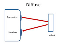
One of the advantages of the diffuse or proximity style photoelectric sensors is the light emitter or light source and the receiver are in the same enclosure thus you only have a single device to mount and wire making installation easier and faster. This is a huge benefit in space restrictive locations or in those applications where you cannot get to both sides of the target as would be required with through-beam or retro-reflective. Since there is, only one device the diffuse photoelectric sensor is typically cost effective as compared to the retro-reflective or through beam sensors.
Applications
• Product height
• Lid presence
• Part presence
• Error proofing
• Fill
Photoelectric -Light On or Dark On Concept (Its basically small selection switch)
In photoelectric sensors, instead of normally open or normally closed we refer to light-on operate or dark-on operate because we are referring to the presence or absence of light at the sensor’s receiver. The output of a light-on operate sensor is on (enabled, high, true) when there is sufficient light on the receiver of the sensor. Conversely, the output of a dark-on operate sensor is on when the light source is blocked or no light can reach the receiver.
There are three modes of operation with photoelectrics: diffuse, retro-reflective, and through-beam; and the sensing mode determines if the sensor is normally light-on or dark-on. Retro-reflective and through-beam sensors function as light-on operate sensors because under normal operating conditions there is a reflector or a light emitter providing a light beam back to the sensor receiver. If no object is blocking the light beam to receiver the output is on, normally closed. If the target or object is in between the reflector or emitter then the light beam can no longer reach the receiver causing the output to turn off.
Since the diffuse mode of operation requires the target or object to reflect the light source back to the receiver, it functions as a dark-on operate, normally open. If no object or target is placed in front of the sensor, no light will be reflected back to the receiver. When the object is present, the output changes state from normally open to closed.
--------------------------------------------------------------------------------------------------------------------------
Ultrasonic Sensors
Ultrasonic sensors are characterized by their reliability and outstanding versatility in industrial applications
Ultrasonic sensors can be used to solve even the most complex tasks involving object detection or level measurement with millimeter precision, because their measuring method works reliably under almost all conditions.
The sensor surface cleans itself through vibration, and i.e sensor is insensitive to dirt. The physical principle the propagation of sound works, with a few exceptions, in practically any environment.
Diffuse and Retroreflective Mode Sensors
Ultrasonic sensors are most commonly used in the diffuse mode.
A single ultrasonic transducer is used as both emitter and receiver and is typically contained in the same housing as the evaluation electronics.
To reliably detect difficult objects, the majority of our diffuse mode sensors can be converted to retroreflective operation via software parameterization. Some ultrasonic sensors are supplied as retroreflective sensors from the outset.
Thru-Beam Sensors
Ultrasonic thru-beam sensors feature an extremely powerful acoustic beam. They offer a large detection range within compact housing dimensions. Unlike diffuse and retroreflective models,
these sensors do not continuously switch between transmission and reception modes or wait for an echo signal to arrive. Thus, their response time is considerably faster, resulting in very high switching frequencies.
Double Sheet Sensors
Double sheet sensors are ultrasonic thru-beam sensors that have been optimized specifically for sheet feed applications, including double sheet detection, label counting, and splice detection.
Double sheet and double material sensors distinguish between empty gaps, one, and two layers of material, including paper, metals, wooden boards, and glass panes.
When performing label detection tasks, the sensors can distinguish between the label backing and the base material.
Applications
• Material handling
• Level measurement
• Food and beverage
• Construction
• Pulp and paper
-----------------------------------------------------------------------------------------------------------Encoders
In many manufacturing and production processes encoders have become established as reliable instruments to ensure precise positioning. They convert rotary movement into digital signals. Encoders use the wear-free photoelectric or magnetic detection. A pulse disc firmly attached to the shaft or a movable magnet carrier ensures this detection.
Incremental Encoder
An incremental encoder is a pulse generator that provides square–wave signals and a zero index. Incremental encoders generate a precisely defined number of pulses per revolution. They are a measure of the angular or linear distance moved. The phase difference between the signals A and B, which are shifted by 90 degrees, allows evaluation of the direction of rotation.


The disc has 2 channels divided into “n” equal angular intervals; alternately opaque and clear. “n” is called resolution or number of counts.
Pulses counted by the processing electronics give the angular position of the rotor. For this purpose 2 square waves A and B are used with a third channel, Z, synchronous with signals A and B giving only one signal per revolution. It allows the user to initialize or reset the count.
Normally 1024 , 5000 or 10,000 PPR (Pulses per revolution) encoders are used
-------------------------------------------------------------------------------------------------------------------------
Absolute Encoder
Absolute encoders provide an absolute numerical value for each angular position even over several revolutions. Even in the event of a power failure the present position is quickly and reliably detected

The absolute encoder supplies the shaft position as a binary code.
The output code is unique for each position. The resolution is equal to 2n (n= number of bit).
The shaft position information is given instantly when power is supplied.
Type of Encoder Mounting
Shaft type with flexible shaft coupling
Hollow shaft encoder for direct mounting (As shown in following picture)
--------------------------------------------------------------------------------------------------------------------------
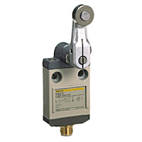
Limit switches automatically monitor and indicate whether the movement limits of a particular device have been exceeded. A standard industrial limit switch is an electromechanical device that contains an actuator linked to a series of contacts. When an object meets the actuator, the limit switch triggers the contacts to either form or break an electrical connection.

Limit Switch Contacts
Control schematics for limit switches usually display symbols to indicate the state of the switch contacts. The most common contact symbols show whether the device has normally open or normally closed limit switch contacts. The symbol for a “normally open held closed” state indicates that the contact has been wired as a normally open contact, but when the circuit is put into its normal off state, part of the machine keeps the contact closed. Likewise, a limit switch that is designated as “normally closed held open” will have a closed wiring design but be held open. Other types of contacts, such as those used in pressure and flow switches, can be configured in a similar way.
For illustrations and more detailed information on the symbols used for electrical contacts, visit Fundamentals of Electrical Engineering and Electronics.
A limit switch is one actuated by contact with a moving machine part. An electronic limit switch senses mechanical motion, but does so using light, magnetic fields, or other non-contact means.
------------------------------------------------------------------------------------------------------------------------
Micro Limit Switches
The micro limit switch, or micro switch, is another type of limit switch commonly found on control circuits. These switches are much smaller than their standard counterparts, allowing them to be installed in narrow or cramped spaces that would normally be inaccessible to other switches.
In summary, field devices are foundational for enabling automation in industrial settings, allowing for seamless data acquisition, control, and process management.
FAQ: Field Devices in Automation
1. What are field devices in automation?
Field devices are components used in industrial automation systems to interact with physical processes. They collect data from the environment (sensors), control systems (actuators), and transmit data (transmitters) to ensure efficient and safe process management.
2. What is the role of sensors in automation?
Sensors measure physical variables like temperature, pressure, flow, and level. These measurements are then transmitted to a control system for monitoring or adjustment of the process.
3. What do actuators do in automation systems?
Actuators convert control signals from a system into physical actions, such as opening a valve, moving a motor, or switching a relay. They directly control a process based on the instructions from the control system.
4. How do transmitters work in automation?
Transmitters convert the raw data from sensors into standardized signals (e.g., 4-20 mA, digital signals) that can be transmitted to a control system for processing and analysis.
5. What communication protocols are used by field devices?
Field devices communicate with controllers and other systems through various industrial communication protocols like HART, Modbus, PROFIBUS, PROFINET, Foundation Fieldbus, and wireless protocols like WirelessHART and Zigbee.
6. What is the purpose of controllers in an automated system?
Controllers like Programmable Logic Controllers (PLCs) or Distributed Control Systems (DCS) process input from sensors and send commands to actuators to ensure that processes operate within desired parameters.
7. What are the most common types of sensors used in industrial automation?
Some common sensors include:
- Temperature sensors (e.g., RTD, thermocouples)
- Pressure sensors (e.g., pressure transducers)
- Flow sensors (e.g., flow meters)
- Proximity sensors (e.g., inductive, capacitive)
8. What is the significance of feedback loops in automation?
A feedback loop ensures that the system constantly monitors a process, adjusts its output based on sensor data, and maintains the system within set operational limits, ensuring stability and accuracy in the process.
9. Why are communication protocols important for field devices?
Protocols define how data is exchanged between field devices and control systems, ensuring reliable, timely, and standardized communication for process monitoring and control.
10. What are wireless field devices, and when are they used?
Wireless field devices transmit data without physical wiring, using technologies like WirelessHART or Zigbee. They are typically used in remote or difficult-to-reach locations where cabling is impractical or expensive.
11. What is the difference between PLC and DCS?
- PLC (Programmable Logic Controller): Used for discrete automation tasks, commonly in manufacturing.
- DCS (Distributed Control System): Used in process automation, managing continuous processes, typically in industries like oil and gas, or power plants.
12. What are smart field devices?
Smart field devices can perform local processing, diagnostics, and self-calibration, often communicating more complex data back to the control system, improving efficiency and reducing maintenance needs.
13. How do safety systems use field devices?
Field devices such as safety switches, pressure sensors, and emergency shut-off valves are integrated into safety systems to monitor and prevent hazardous situations, ensuring safe operation of industrial processes.
14. What is a 4-20 mA signal, and why is it used?
The 4-20 mA signal is a standard analog signal used to transmit data from field devices to control systems. It is favored for its simplicity and robustness, with the lower range of 4 mA allowing detection of a wire break.


Thanks admin for this wonderful post, full of ideas about "china micro switch manufacturer". The post is written in very a good manner and it entails many useful information for me. I appreciated what you have done here.
ReplyDelete