Earthing System | Types of Earthing System | Maintenance Free Earthing | Earthing Wire | Plate Earthing | Pipe Earthing
Earthing system is a critical aspect of electrical systems, as it helps to protect both people and equipment from dangerous electrical faults. An earthing system is an essential safety measure used in electrical systems to protect people and equipment from electrical hazards. A well-designed earthing system can provide a low resistance path to ground, which helps to divert electrical faults away from the system.
Earthing System | Types of Earthing System | Maintenance Free Earthing |Earthing Wire | Plate Earthing | Pipe Earthing
- Earthing, also known as grounding, is a crucial safety measure in electrical installations.
- The primary principle of earthing is to provide a low resistance path for the flow of electric current to the earth.
- The earthing system consists of connecting the metallic parts of an electrical system to a conductive plate buried in the earth or a metallic water pipe.
- Earthing helps protect electrical appliances and people from electric shocks by diverting the current to the ground, which can absorb it harmlessly.
- A properly designed and installed earthing system also helps improve the quality of the electrical signal and reduce electromagnetic interference.
- There are different types of earthing systems, including TN, TT, and IT, which vary in their implementation and effectiveness.
- Earthing is essential in various settings, including homes, offices, industries, and power plants, among others.
- The earthing system needs to be regularly tested and maintained to ensure its effectiveness and compliance with safety regulations.
- Failure to implement proper earthing can result in equipment damage, fires, and, in extreme cases, electrocution and death.
Different Types of Earthing
Plate Earthing
Plate earthing is the most common type of earthing used in residential and commercial buildings. It involves burying a metal plate, usually made of copper or galvanized steel, in the ground. This type of earthing is suitable for low voltage applications, and its resistance should be kept below 5 ohms.


Pipe Earthing
Pipe earthing involves using a metal pipe to create a low-resistance path to the ground. This type of earthing is suitable for both low and high voltage applications and is often used in industrial settings. The resistance of pipe earthing should be kept below 1 ohm.


Rod Earthing
Rod earthing involves burying a metal rod, usually made of copper or galvanized steel, in the ground. This type of earthing is suitable for high voltage applications and is often used in power plants and substations. The resistance of rod earthing should be kept below 1 ohm.

Electronic Earthing
Electronic earthing for PLCs (Programmable Logic Controllers) is an essential aspect of ensuring the proper functioning and reliability of the electronic control system. PLCs are used to control various industrial processes, and their proper functioning is crucial to ensure efficient operation and safety.
Electronic earthing for PLCs involves creating a low resistance path for electrical faults to ground. This helps to protect the PLC and other equipment from damage due to electrical faults. There are different types of electronic earthing methods available, and the choice depends on the specific application and the environment.
For Analog signals connected through Screened cable always tie one end of screen to earth (not both end) as both end earth pits may have potential difference. It will cause current flow through screen leading noise interference.
One common electronic earthing method is to use a ground wire that connects the PLC enclosure to a ground rod or a ground plate. This creates a low resistance path for any electrical faults that may occur in the system.
Another method is to use a separate ground bus bar that is connected to the PLC enclosure and other equipment in the system. This helps to isolate the PLC and other equipment from electrical noise that may be present in the system.
System/Neutral earthing
It is provided basically for the purpose of preserving the security of the system by ensuring that the voltage on each live conductor is restricted to such a value with respect to potential of general mass of earth as is consistent with level of insulation applied and other safety equirements.
Equipment Earthing
Equipment earthing, also known as equipment grounding, is a safety measure used in electrical systems to protect people and equipment from electrical hazards. Equipment earthing involves creating a low resistance path to ground, which helps to divert electrical faults away from the equipment. It is the term used for electrical connection of the non-current carrying metallic parts in the neighbourhood of electrical circuits of apparatus/equipments to general mass of earth.
The objective of equipment earthing is to ensure effective operation of protective gear in the event of leakage through such metal work, the potential of which with respect to neighbouring objects may attain a value which would cause danger to life or risk of fire.
There are several methods of equipment earthing, including:
Direct earth connection: This involves connecting the equipment directly to an earth electrode, which is buried in the ground. This creates a low resistance path to ground and helps to protect the equipment from electrical faults.
Earth leakage circuit breaker (ELCB): An ELCB is a safety device that detects electrical leakage in the circuit and disconnects the power supply to the equipment. This helps to prevent electrical shocks and protects the equipment from damage due to electrical faults.
Residual current device (RCD): An RCD is a safety device that detects the imbalance of current in the circuit and disconnects the power supply to the equipment. This helps to protect the equipment from damage due to electrical faults and prevents electrical shocks to people.
Soil Resistivity
The resistance to earth of a given electrode depends upon the electrical resistivity of the soil in which it is installed, which in turn is determined by the following factors
- Nature of soil
- Extent of moisture
Nature of Soil
If site does not have the following types of soil in the following order of preference then the pit shall be prepared with the soil :
- Wet marshy ground containing refuse, cinders, brine waste etc.
- Clayey soil or loam mixed with small quantities of sand.
- Clay and loam mixed with varying proportions of sand,gravel and stones.
- Damp and wet sand pit.
Dry sand, gravel, chalk, lime stone, granite and very stony ground shall be avoided, and also all locations where virgin rock is very close to the surface.
A site shall be chosen that is not naturally well-drained. Care also shall be taken to avoid a site kept moist by water flowing over it as the beneficial salt may be entirely removed from the soil in such situation.
If an imported fill exercise (such as filling/levelling by earth/slag brought from elsewhere) has been carried out, in these cases, deeper driving of the electrode may be necessary to reachnlayers of reasonable resistivity and also to reach stable ground,such that the value of the electrode resistance remains stable if the top layers of the ground dry out.
Extent of moisture
Moisture content is one of the controlling factors in earth resistivity. It is established that above about 20% moisture, the resistivity is very little affected, while below 20% the resistivity increases very abruptly with the decrease in moisture content.(Refer Fig.9 of IS:3043-latest version). A difference of a few percent moisture will, therefore, make a very marked difference in the effectiveness of earth connection if the moisture content falls below 20 %. The normal moisture content of soils ranges from 10% in dry seasons to 35% in wet seasons, and an approximate average may be perhaps 16 to 18 percent. It should be recognised, however, that moisture alone is not the predominant factor in the low resistivity of soils; but the value of high moisture content in soils is advantageous in increasing the solubility of existing natural elements in the soil, and in providing for the solubility of ingredients which may be artificially introduced to improve the soil conductivity.
Maintenance Free Earthing
Maintenance Free Earthing, also known as Maintenance Free Earth System or MFES, is a type of earthing system that requires little to no maintenance over its lifetime. MFES is typically used in high voltage electrical systems, where frequent maintenance and inspection of the earthing system may be difficult or dangerous.
MFES uses a combination of specially designed conductors, electrodes, and backfill materials that create a low resistance path to ground. The system is designed to maintain a low resistance value throughout its lifetime, without the need for regular maintenance or inspection.

One common type of MFES is the Chemical Earthing System, which uses a conductive backfill material such as Bentonite or Epsom Salt, along with a specially designed electrode made of copper or galvanized steel. The chemical backfill material helps to maintain a low resistance value over time, while the electrode provides a strong and durable connection to ground.
Another type of MFES is the Maintenance Free Earth Pit, which uses a specially designed earth pit made of concrete or other materials that resist corrosion and damage. The earth pit contains the electrode and backfill material, and is designed to provide long-lasting and reliable earthing without the need for maintenance or inspection.
Chemical (Maintenance free) Earth Pit Station:
Material required for preparing Chemical (maintenance free) earth pit shall be as follows:
1) Pipe In Pipe Electrode: shall be having parameter as follows:
- Length of electrode- 3(three) meters.
- Inner dia. of electrode- 42 mm approx.
- Outer dia. of electrode- 80 mm approx.
- wall thickness - 3 mm minimum
- Anti-corrosive crystalline conductive mixture tightly filled.
2) Ground enhancing backfill Compound surrounding earth electrode (bentonite content shall be negligible). Properties of compound material should be as follows:
- High conductivity, improves earth’s absorbing power and humidity retention capability.
- Non-corrosive in nature having low water solubility but highly hygroscopic.
- Resistivity of less than 0.2 ohms-meter.
- Does not depend on the continuous presence of water to maintain its conductivity.
- Permanent & maintenance free and in its “set form”, maintains constant earth resistance with time.
- Does not dissolve, decompose or leach out with time.
- Does not require periodic charging treatment nor replacement and maintenance.
- Does not pollute the soil or local water table and meets environmental friendly requirements for landfill.
- Non explosive.
- Does not cause burns, irritation to eye, skin etc
MFES Benefits
MFES provides several benefits over traditional earthing systems, including:
Lower maintenance costs: MFES requires little to no maintenance over its lifetime, which can result in significant cost savings compared to traditional earthing systems that require frequent inspection and maintenance.
Improved safety: MFES provides a reliable and consistent low resistance path to ground, which helps to protect people and equipment from electrical hazards.
Long-lasting performance: MFES is designed to maintain a low resistance value over its lifetime, providing reliable performance and protection for high voltage electrical systems.
Good earthing resistance is essential to ensure that electrical faults are quickly detected and cleared. The resistance of earthing should be regularly measured and maintained below the recommended values. For example, the resistance of plate earthing should be kept below 5 ohms, pipe earthing below 1 ohm, and rod earthing below 1 ohm.
Annual measurement and maintenance practices are essential to ensure that earthing systems are functioning correctly. This involves regular inspection of the earthing system, measurement of earthing resistance, and cleaning and tightening of connections. Any defects or faults should be promptly rectified to ensure that the earthing system is working effectively.
INSPECTION
All earth connections shall be visible for inspection.
All earthing systems shall be visually inspected before the testing.In course of inspection, the following shall be observed :
- Whether there are distinct earth pits for equipment and neutral earthing, Electronic equipment, computers.
- Whether two distinct leads have been terminated at the respective earth pits.
- Overall cleanliness of the area,
- Condition of earthing resistor and link there-of,
- All surfaces where connections are made are free of grease, paint, dirt or any other foreign materials.
- Condition of earth pit and masonry work,
- Electrode connection for their rigidity, and signs of detoriation, if any,
- Condition of the earth electrode, exposed above the ground level, the connectivity whether the pipe got rusted, pipe top cap etc.
- Earth pits are to be covered with R C slabs or iron plates.
- Group earth pits are barricaded.
MAINTENANCE
Artificial (Chemical) Treatment of Soil
Soil resistivity depends upon local conditions. Water alone, in the absence of natural salt, can not provide adequate conductivity. Hence, earth resistance is reduced by means of mixing common salt homogenously with fine sand in suitable proportion. Addition of water into this salt solution causes gradual diffusion of salt in the soil around the electrode and thus soil resistivity is reduced.
Three to four buckets of water shall be poured once in every month to keep the soil sourounding the earth electrode, wet. This addition of water shall suffice to keep the soil resistivity low.
If during testing, the resistance value of the station/system is found high (ie. above 1 Ω ), water shall be poured and the earth resistance shall be measured after 15 days of water pouring.
From the record maintained for each earthing system, if the earthing resistance is found consistently higher than the prescribed value, then rework on earthing system and chemical treatment of the earthing station shall be carried out.
The periodicity of chemical treatment shall be determined by measurements of earth resistance based on the routine test record.

All nut-bolt connections between equipment/neutral and earth electrode shall be checked and tightened.
Any defects or irregularities observed during the periodic inspection as per clause shall be attended to within a reasonable time.
TESTING
The resistivity of earth varies over a wide range depending on the nature of soil condition and its moisture content. It is therefore, advisable to conduct earth resisitivity tests during the dry season in order to get conservative results. A record shall be maintained for the initial earthing resistance and subsequent measurements of earthing resistances.
a) Earthing systems of voltage >650 Volts: All earthing systems shall be tested for resistance with the help of an "Earth Tester" on a dry day during the dry season, not less than once a year for high and extra high voltages (>650 Volts).
b) Earthing systems of voltage <=650 Volts: All earthing systems shall be tested for resistance with the help of an "Earth Tester" on a dry day during the dry season, not less than once every two years for low , medium voltages(<=650 Volts).
For testing of an earthing system, the following steps shall be followed :
a) Study the Earthing System drawing permanently displayed in the installation and familiarize with the following:
i) Whether system earthing or equipment earthing, or Electronic or computer earthing.
ii) Interconnection between electrodes
b) Identify the earthing station group to be tested; if the combined resistance value is found high (over 1 ohm) during group testing then only individual station shall be tested.
c) Ensure that earthing pit area is clean and dry,
i) In case of system earthing, the test electrode shall be separated from the earthing system by operating the isolating link before the test. Proper care shall be taken during operation of isolating link and it shall be ensured that earth lead from isolating link to electrode have no power or not charged. This shall be checked with the help of a Power Tester.
ii) "CAUTION" tag shall be fixed at the isolation point.
iii) Clearance on the prescribed form "Permit to Work” and clearance to the testing personnel on the prescribed form "Clearance to work on Electrical Equipment" shall be obtained before starting the job from authorized concerned person.
d) Testing by Earth Tester"
i) Voltage shall be checked on grounding electrode with respect to the nearest earthing point and this shall be within 5 -10 volts. If the voltage is more than 10V then test should not be conducted. For Testing rubber mat and rubber hand gloves are to be used.
ii) All other earth electrodes shall be disconnected from the test electrode.
iii) Only insulated leads shall be used for connecting the electrodes.
iv) The leads shall be as short as possible.
e) i) All the current and potential electrodes shall be so placed that they are independent of the resistance area of the electrode under test. If the electrode under test is in the form of a pipe or plate, the current electrode shall be placed at least 30 meters away from it and the potential electrode midway between them.
ii) The auxiliary electrode normally considered as water pipes where water connection is through or railway line, structure or any other unique earth pit which is not connected with the system. The first Auxiliary pit or electrode should have minimum distance of 15 meter from the pit.
f) After completion of test :
i) All disconnected points shall be restored and tightened and again combined value should be tested
ii) The caution tag shall be removed.
iii) Isolating link shall be made ON.
iv) The clearance shall be cancelled.
The value of resistance to earth for each group of connected earthing pits shall not be more than 1 ohm for all range of voltages.
Records of such test values shall be properly maintained for all future references as and when required.
The earth pit no., latest earth resistance (without disconnecting earth pit)),date of testing and due date of testing shall be displayed on existing name plate.
Electrical grounding as a safety measure used to help prevent people from accidentally coming in contact with electrical hazards.
For example refrigerator. It is a metal box standing on rubber feet with electricity running in and out of it. We use magnets to hang our child’s latest drawing on the metal exterior. The electricity running from the outlet and through the power cord to the electrical components inside the refrigerator are electrically isolated from the metal exterior or chassis of the refrigerator.
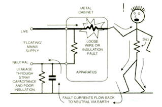
If for some reason the electricity came in contact with the chassis, the rubber feet would prevent the electricity from going anywhere and it would sit waiting for someone to walk up and touch the refrigerator. Once someone touched the refrigerator the electricity would flow from the chassis of the refrigerator and through the unlucky person possibly causing injury.
Grounding is used to protect that person. By connecting a green ground wire from the metal frame of the refrigerator, if the chassis inadvertently becomes charged for any reason, the unwanted electricity will travel through the wire back to your electrical panel, and tripping the circuit-breaker (ELCB or RCBO) stopping the flow of electricity. Additionally, that wire must be connected to something that is in turn connected to the earth or ground outside. Typically this connection is a grounding electrode, such as a ground rod.
Earthing Wire
Following is typical earting wire used


The wire should also be made of a material that has good electrical conductivity and corrosion resistance, such as copper or galvanized steel.
The size of the earthing wire depends on several factors, including the size of the electrical system, the maximum fault current, and the length of the wire. In general, larger electrical systems and higher fault currents require larger earthing wires with a larger cross-sectional area.
For example, a medium-sized commercial building with a maximum fault current of 10 kA might require an earthing wire with a cross-sectional area of 50 mm². The wire would be made of copper, which has good electrical conductivity and corrosion resistance, and would be buried at least 600mm below the ground surface to ensure proper contact with the soil.
The electrician would also install a suitable earthing electrode, such as a copper rod or plate, and connect the earthing wire to it to provide a low resistance path to ground.
In contrast, a small residential building with a maximum fault current of 2 kA might require an earthing wire with a cross-sectional area of 4 mm². The wire would also be made of copper and buried at least 600mm below the ground surface, with a suitable earthing electrode installed and connected to the wire. Regular inspections and maintenance would also be performed to ensure the effectiveness of the earthing system.
Conclusion
Maintenance Free Earthing is a type of earthing system that provides long-lasting and reliable protection for high voltage electrical systems, without the need for frequent maintenance or inspection. MFES uses specially designed conductors, electrodes, and backfill materials to create a low resistance path to ground, and provides several benefits over traditional earthing systems.
Proper earthing is crucial for safe and effective operation of electrical systems. There are different types of earthing available, and each has its own specific applications. Good earthing resistance is essential, and regular measurement and maintenance practices should be carried out to ensure that the earthing system is functioning correctly.
Frequently Asked Questions (FAQ)
What are the 5 earthing systems?
Solid-earthed neutral: Neutral point is connected to the earth through a direct low-impedance conductor.
Unearthed neutral: Neutral point is not connected to the earth, so there is no intentional path for fault currents to earth.
Resistance-earthed neutral: Neutral point is connected to earth through a resistance, limiting the fault current to a safe level.
Reactance-earthed neutral: Neutral point is connected to earth through a reactor, limiting the fault current to a safe level while also reducing transient overvoltages.
Earthing transformers: Used to create a neutral point for an ungrounded power system by connecting zigzag transformers between the phases and earth, providing a path for ground fault current.
What are the 4 types of earthing?
Plate Earthing: A copper or galvanized iron plate is buried vertically in the ground to provide a low-impedance path to the earth.
Pipe Earthing: A pipe made of galvanized iron is used as an electrode to create a low-resistance path to the ground.
Mat Earthing: A flat copper plate or mesh is used as an electrode, which is buried in a shallow trench filled with charcoal and salt to reduce soil resistance.
Rod Earthing: A long and narrow electrode made of copper or galvanized iron is driven vertically into the earth to create a low-impedance path for electrical current
What are the 3 earthing systems?
The IEC 60364 standard has established three categories of earthing systems: TT, IT, and TN systems.
TT System: The neutral of the electrical supply is connected to a local earth electrode, and the exposed conductive parts are connected to another separate earth electrode.
IT System: The neutral of the electrical supply is connected to earth, and the exposed conductive parts are isolated from earth.
TN System: The neutral of the electrical supply is directly connected to earth, and the exposed conductive parts are also connected to earth.
What is the principle of earthing?
The principle of earthing, also known as grounding, is to provide a low resistance path for the flow of electric current to the earth. This is done to protect electrical appliances and people from electric shocks by diverting the current to the ground, which can absorb it harmlessly. The process involves connecting the metal parts of an electrical system to a conductive plate buried in the earth or a metallic water pipe, which acts as a ground. Earthing is an essential safety measure in electrical installations, and it also helps to improve the quality of the electrical signal and reduce electromagnetic interference.
What is the function of earthing?
The function of earthing, also known as grounding, is to provide a low resistance path for the flow of electric current to the earth, which helps protect electrical appliances and people from electric shocks. When an electrical system is properly grounded, any excess current or voltage will be safely conducted to the ground, reducing the risk of damage or injury. Additionally, earthing can improve the quality of the electrical signal and reduce electromagnetic interference. Earthing is a crucial safety measure in electrical installations and is required by various safety regulations in different settings, including homes, offices, industries, and power plants.


Post a Comment