Rectifier | Rectifier Regulator | Diode Rectifier | Full Wave Bridge Rectifier | Rectifier Circuit | Regulator Rectifier | Define Rectifier | Rectifier Diode Bridge | Bridge Rectifier Circuits | How Does a Rectifier Work| Full Wave Rectifier Circuit | In Half Wave Rectifier How many Diodes are Used | Half Wave Rectifier | Half Wave Rectifier Diagram | Ripple Factor of Half Wave Rectifier | What is Half Wave Rectifier
A rectifier regulator is an essential component of an electrical system that converts alternating current (AC) to direct current (DC) and regulates the voltage output. It's commonly used in motorcycles and other small vehicles to ensure proper functioning of the electrical system and prevent overcharging of the battery. A rectifier regulator can come in different forms, such as a diode rectifier, full wave bridge rectifier, or regulator rectifier circuit. Understanding the different types of rectifiers and their functions is important in maintaining the health of your electrical system. In this article, we will provide a comprehensive guide to rectifier regulators, their types, and common issues associated with them.
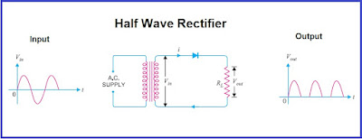
The rectifier part of the regulator converts the AC voltage from the alternator or generator into DC voltage. The rectifier can be a half-wave or full-wave rectifier, depending on the design of the regulator. In a half-wave rectifier, only one half of the AC waveform is converted into DC, while in a full-wave rectifier, both halves of the AC waveform are converted into DC.
The regulator part of the rectifier regulator is responsible for regulating the output voltage to a constant level. The regulator monitors the output voltage and adjusts it as necessary to maintain a stable voltage level. The regulator can be a shunt regulator or a series regulator, depending on the design of the regulator.
A shunt regulator controls the voltage across a shunt resistance, while a series regulator controls the voltage by adjusting the resistance in the output circuit. A shunt regulator is generally less expensive and simpler to implement, but it is less efficient than a series regulator.
Uncontrolled Rectifier
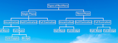
An uncontrolled rectifier is a type of rectifier in which the output voltage is not regulated or controlled. The output voltage is dependent on the input voltage and load characteristics. Uncontrolled rectifiers are simple, low cost, and widely used in applications where voltage regulation is not required. There are two types of uncontrolled rectifiers:
In Half Wave Rectifier How many Diodes are Used | Half-Wave Rectifier | Half Wave Rectifier Diagram | Ripple Factor of Half Wave Rectifier | What is Half Wave Rectifier
A half wave rectifier is a type of rectifier circuit that converts AC (alternating current) input voltage into DC (direct current) output voltage. In a half wave rectifier circuit, only one diode is used.The diode is connected in series with the load resistor and the AC input voltage source. During the positive half cycle of the AC voltage, the diode conducts current and allows it to flow through the load resistor, resulting in a positive voltage output. During the negative half cycle of the AC voltage, the diode is reverse biased and does not conduct current, resulting in zero voltage output.
The output voltage of a half wave rectifier is not pure DC, as it contains a large ripple component due to the fact that only half of the AC waveform is being rectified. The ripple voltage can be reduced by using a filter capacitor in parallel with the load resistor.
Ripple factor of Half Wave Rectifier
Full-Wave Rectifier:
The full-wave rectifier is more efficient than the half-wave rectifier, as it rectifies the entire input waveform. There are two types of full-wave rectifiers:
Center-Tap Full-Wave Rectifier:
A center-tap full-wave rectifier uses a center-tapped transformer and two diodes to rectify the input waveform. The center-tap of the transformer is connected to the load resistance, and the two diodes are connected to the outer ends of the secondary winding. During the positive half-cycle of the input voltage, the diode connected to the upper end of the secondary winding conducts, and during the negative half-cycle, the diode connected to the lower end of the secondary winding conducts. The output voltage is equal to the peak value of the input voltage multiplied by the rectification factor, which is approximately 0.637.
Bridge Full-Wave Rectifier:
A bridge full-wave rectifier uses four diodes arranged in a bridge configuration to rectify the input waveform. The output voltage is equal to the peak value of the input voltage multiplied by the rectification factor, which is approximately 0.9. Bridge full-wave rectifiers are more efficient than center-tap full-wave rectifiers, as they eliminate the need for a center-tapped transformer.
Controlled Rectifier:
A controlled rectifier is a type of rectifier in which the output voltage can be controlled by varying the input voltage. Controlled rectifiers are used in applications where voltage control is required, such as motor speed control, DC power supplies, and battery charging systems. There are two types of controlled rectifiers:
Thyristor Controlled Rectifier (TCR):
A thyristor controlled rectifier (TCR) is a type of controlled rectifier in which the rectification process is controlled by thyristors. Thyristors are semiconductor devices that can be turned on and off using a control signal. By varying the control signal, the output voltage can be controlled. TCRs are highly efficient and can be used in high-power applications.
Silicon Controlled Rectifier (SCR): A silicon controlled rectifier (SCR) is a type of thyristor that can be used for rectification purposes. SCRs are highly reliable and can be used in applications such as motor control, lighting systems, and power supplies. SCRs are less efficient than TCRs but are simpler to implement.
Three Phase Rectifiers:
Three-phase rectifiers use three-phase AC input and a rectifier circuit to convert the AC voltage to DC voltage. The rectifier circuit can be either uncontrolled or controlled.
Uncontrolled Rectifiers: Uncontrolled rectifiers use diodes to rectify the three-phase AC input. The diodes conduct current during alternate half cycles of the input waveform. The output waveform is pulsating DC with a DC level equal to 1.35 times the peak value of the input AC voltage. The main components of an uncontrolled rectifier are diodes and a load resistor.
Controlled Rectifiers: Controlled rectifiers use thyristors (SCRs) to rectify the three-phase AC input. The thyristors can be triggered to conduct current during a specific part of the input waveform. The output waveform can be controlled by changing the triggering angle of the thyristors. The main advantage of this type of rectifier is the ability to control the output voltage and current. The main components of a controlled rectifier are thyristors, triggering circuitry, and a load resistor.
Controlled Rectifiers : Controlled rectifiers are those in which the output voltage can be controlled by varying the input voltage. They are widely used in applications where voltage control is required, such as in motor speed control, DC power supplies, and battery charging systems.
Thyristor Controlled Rectifiers (TCR): In TCRs, the rectification process is controlled by thyristors. Thyristors are semiconductor devices that can be turned on and off using a control signal. By varying the control signal, the output voltage can be controlled. TCRs are highly efficient and can be used in high-power applications.
Silicon Controlled Rectifiers (SCR): SCRs are a type of thyristor that can be used for rectification purposes. They are highly reliable and can be used in applications such as motor control, lighting systems, and power supplies.
Uncontrolled Rectifiers In uncontrolled rectifiers, the output voltage is not controlled and depends only on the input voltage and load characteristics. They are simple and cost-effective, and are widely used in applications where voltage control is not required. Uncontrolled rectifiers are further classified into two types:
Half Wave Rectifiers: Half wave rectifiers are the simplest type of rectifiers, in which only half of the input waveform is rectified. They consist of a single diode and a load resistance. They are used in applications where low power is required and cost is a critical factor.
Full Wave Rectifiers: Full wave rectifiers are more complex than half wave rectifiers, and rectify the entire input waveform. They consist of two diodes and a center-tapped transformer or a bridge rectifier circuit. They are widely used in applications such as battery chargers, power supplies, and motor control.
Bridge Rectifiers Bridge rectifiers are a type of full wave rectifier that use four diodes arranged in a bridge configuration. They are more efficient than center-tapped full wave rectifiers, as they eliminate the need for a center-tapped transformer. Bridge rectifiers are widely used in applications such as battery chargers, power supplies, and lighting systems.
Center-Tapped Rectifiers Center-tapped rectifiers are a type of full wave rectifier that use a center-tapped transformer and two diodes to rectify the input waveform. They are less efficient than bridge rectifiers, as they require a center-tapped transformer. Center-tapped rectifiers are widely used in low power applications such as battery chargers and power supplies.
The ratings for each type of rectifier depend on the specific application and the load characteristics. Key ratings to consider include the maximum input voltage, maximum output voltage, maximum output current, and maximum power rating. These ratings must be selected based on the requirements of the application, to ensure safe and reliable operation of the rectifier.
Calculation of output voltage of each type of rectifier:
Half-wave rectifier:
In a half-wave rectifier, only one half of the AC input voltage is used, and the other half is blocked. The output voltage of a half-wave rectifier can be calculated using the following formula:
Vout = Vp x (|sinθ|)
Where Vp is the peak input voltage and θ is the angle between the input voltage and the reference axis (usually taken as zero). The absolute value of the sine function is used to ensure that the output voltage is always positive.
Full-wave rectifier:
In a full-wave rectifier, both halves of the AC input voltage are used, but they are rectified separately. The output voltage of a full-wave rectifier can be calculated using the following formula:
Vout = Vp x (2/π) x (|sinθ1| + |sinθ2|)
Where Vp is the peak input voltage, θ1 is the angle between the input voltage and the reference axis for the positive half cycle, and θ2 is the angle for the negative half cycle. Again, the absolute value of the sine function is used to ensure that the output voltage is always positive.
Bridge rectifier:
A bridge rectifier is a type of full-wave rectifier that uses four diodes arranged in a bridge configuration. The output voltage of a bridge rectifier can be calculated using the same formula as a full-wave rectifier:
Vout = Vp x (2/π) x (|sinθ1| + |sinθ2|)
Where Vp is the peak input voltage, θ1 is the angle between the input voltage and the reference axis for the positive half cycle, and θ2 is the angle for the negative half cycle.
Summary
In Summary, the output voltage of a rectifier depends on the type of rectifier circuit and the input voltage. Half-wave rectifiers only use one half of the input voltage, while full-wave rectifiers and bridge rectifiers use both halves. The output voltage can be calculated using specific formulas based on the type of rectifier.
Frequently Asked Questions
What is a rectifier regulator?
What are the symptoms of a faulty regulator rectifier?
- Battery not charging properly or draining quickly
- Dim or flickering headlights
- Electrical system not functioning properly
- Overheating of electrical components
- Burnt smell coming from the regulator rectifier
- If you are experiencing any of these symptoms, it's important to have your electrical system inspected by a professional to determine if the regulator rectifier is the cause.


Post a Comment