1 Minute, 5 Minute, 10 Minute and 15 Minute Timer Circuit Diagram | 555 Timer IC | 555 Timer | Astable Multivibrator Using 555 Timer | Monostable Multivibrator Using 555 Timer
As the world is becoming more and more digital, the need for electronic timers is increasing. Electronic timers are used in various fields like home appliances, automobiles, and industrial automation. The 555 timer IC is a versatile integrated circuit that can be used as a timer, oscillator, and flip-flop. In this article, we will discuss the 15 minute timer circuit diagram, working, and applications using the 555 timer IC.
The 555 Timer IC is a versatile integrated circuit that can be used in a variety of applications such as timer circuits, pulse generators, and oscillators. It is a popular choice for electronic hobbyists and professionals due to its low cost, simplicity, and reliability.
555 Timer IC can be configured in three different states:
Astable Multivibrator: In this configuration, the 555 timer IC operates as a free-running oscillator that generates a continuous square wave output. The frequency and duty cycle of the output can be adjusted by changing the values of the external components connected to pins 2, 3, and 6.
Monostable Multivibrator: In this configuration, the 555 timer IC produces a single pulse of a fixed duration in response to a trigger input. The duration of the pulse can be adjusted by changing the values of the external components connected to pins 2, 6, and 7.
Bistable Multivibrator: In this configuration, the 555 timer IC operates as a flip-flop that toggles between two stable states in response to trigger inputs. This configuration is often used in applications such as digital logic circuits and electronic switches.
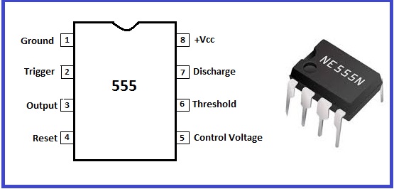
The pinout diagram of the 555 timer IC
The 555 timer IC is an integrated circuit that has eight pins, each of which serves a different function. The pinout diagram of the 555 timer IC is as follows:
Pin 1: Ground (GND)
Pin 2: Trigger (TRIG)
Pin 3: Output (OUT)
Pin 4: Reset (RESET)
Pin 5: Control Voltage (CV)
Pin 6: Threshold (THRES)
Pin 7: Discharge (DIS)
Pin 8: Vcc (Positive Supply Voltage)
555 Timer IC: This versatile integrated circuit will be the heart of your timer circuit. It can be configured in a variety of ways to create different timing sequences.
LED: An LED can be used to indicate when the timer is running, or to signal the end of the timing cycle.
Capacitor (1000 μF): This component is used to stabilize the voltage in the circuit, ensuring consistent timing intervals.
Variable resistor: Also known as a potentiometer, this component allows you to adjust the timing intervals of your circuit.
Push button: This is used to trigger the timer circuit and start the timing sequence.
Resistor: A resistor is used to limit the flow of current in the circuit, protecting your components from damage.
Power supply: power source / battery to operate timer circuit. Make sure to choose a power supply that is appropriate for your circuit's voltage and current requirements.
Connecting wires: Finally, need wires to connect all of the components together and create a functional circuit.

1-Minute Timer Circuit | 5-Minute Timer Circuit | 10-Minute Timer Circuit| 15-Minute Timer Circuit:
The 1-minute timer circuit is a simple electronic circuit that can be used for various purposes, such as turning off a device after a fixed time or triggering an alarm after a set time interval. The circuit diagram consists of a 555 timer IC, a capacitor, and a few resistors. The capacitor is charged through the resistors, and the timer IC triggers when the capacitor voltage reaches a specific threshold. The output of the timer can be used to drive a relay or an LED.
Refer below table and change R1 for 5 Minute, 10 Minute & 15 Minute Timer as per calculation below

Application:
The timer circuits discussed in this article have a wide range of applications in various electronic devices and systems. Here are some examples of their applications:
Automatic Lighting Control: The 1-minute, 5-minute, 10-minute, and 15-minute timer circuits can be used to control the duration of lighting in various settings such as homes, offices, and public places. For instance, the 5-minute timer circuit can be used to control the duration of hallway lights, while the 15-minute timer circuit can be used to control the duration of parking lot lights.
Motor Control: Timer circuits can also be used to control the duration of motors in various devices such as fans, pumps, and conveyors. For instance, the 10-minute timer circuit can be used to control the duration of a water pump in a garden.
Alarm Systems: Timer circuits can also be used to trigger alarms after a set time interval. For instance, the 1-minute timer circuit can be used to trigger an alarm after a user-defined time interval, which can be useful in many applications such as kitchen timers, fire alarms, and security systems.
Home Automation: Timer circuits can be integrated into various home automation systems to control the duration of devices such as lights, fans, and heating systems.
Industrial Automation: Timer circuits are also widely used in various industrial automation systems to control the duration of devices such as pumps, conveyors, and motors.
Conclusion
Timer circuits are essential components in many electronic devices and applications. They allow for precise timing control, making them ideal for various tasks. The 1-minute, 5-minute, 10-minute, and 15-minute timer circuits are just a few examples of the many types of timer circuits that exist. By understanding the circuit diagrams and explanations provided in this article, you can gain a deeper appreciation of these useful circuits and their applications.
Frequently Asked Questions (FAQ)
What are the applications of timing circuits?
Timing circuits are used in a wide variety of applications, such as controlling the speed of motors, generating pulses, controlling the duration of signals, and more. They are essential components in many electronic devices and systems.
What is the basic working of timer circuit?
A timer circuit works by using a combination of resistors, capacitors, and a timing IC like the 555 Timer IC. The timing IC produces an oscillating signal which is then used to trigger a transistor or other switching device. The timing of the signal can be adjusted by changing the values of the resistors and capacitors in the circuit.
What is IC 555 and its application?
IC 555 is a versatile integrated circuit that is commonly used in timer, oscillator, and pulse generation applications. It can be configured in various modes, including astable, monostable, and bistable modes. Some common applications of IC 555 include LED flashers, tone generators, and alarm circuits.
What is the use of timer in electrical circuit?
Timers are used in electrical circuits to control the timing of events, such as turning on or off a motor or a light, or triggering a sensor at specific intervals. They are commonly used in automation systems, lighting controls, and other applications where precise timing is critical.
1-15 Minute Timer Circuit using IC 555 - Instructions
This circuit uses an IC 555 timer to generate a time delay of 1-15 minutes. Here's how to build it:
Materials
- IC 555 timer
- 10K ohm potentiometer
- 1K ohm resistor
- 10uF capacitor
- 100uF capacitor
- LED
- 9V battery
- Breadboard
- Jumper wires
Instructions
- Connect the IC 555 timer to the breadboard.
- Connect the 10K potentiometer to pins 6, 7, and 8 of the IC, with the middle pin (7) connected to pin 2 of the IC.
- Connect the 1K resistor between pins 6 and 2 of the IC.
- Connect the 10uF capacitor between pins 2 and 1 of the IC.
- Connect the 100uF capacitor between pins 5 and 1 of the IC, with the negative side of the capacitor connected to pin 1.
- Connect the LED to pins 3 and 4 of the IC, with the negative side of the LED connected to pin 3.
- Connect the 9V battery to the breadboard.
- Connect a jumper wire from the positive rail of the breadboard to pin 8 of the IC.
- Connect a jumper wire from the negative rail of the breadboard to pin 1 of the IC.
- Adjust the potentiometer to set the desired time delay between 1 and 15 minutes.
- The LED will turn on when the time delay is complete.


Post a Comment